Welcome to the official website of Jinzhou Heli Vacuum Metallurgy Co., Ltd!

Email:qj7900@163.com
Service Hotline:+86 416-4185882 +86 13804167900

Three-chamber vacuum melting furnace Vacuum melting furnace Vacuum atomization powder making furnace

Vacuum atomization powder furnace
Category:
Keywords:
Vacuum atomization powder furnace
Hotline:
Vacuum atomization powder furnace
1. Principle of Vacuum Atomization Powder Production Furnace:
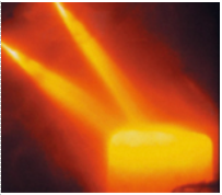
The principle of vacuum atomization is that under vacuum conditions or in a gas-protected environment, metals and metal alloys are melted. The molten metal flows down from the insulation crucible and the flow guide nozzle, and is atomized into numerous fine droplets by a high-pressure gas stream through the nozzle. These fine droplets solidify into spherical and sub-spherical particles during flight, and then are screened and separated to prepare metal powders of various particle sizes.
Metal powder technology is a widely used production method in various industries today.
Alloys manufactured using powder metallurgy techniques have a wide range of applications, such as welding and brazing alloys for the electronics industry, nickel, cobalt, and iron-containing high-temperature alloys for aircraft, hydrogen storage alloys and magnetic alloys, and reactive alloys such as titanium for sputtering target production.
The process steps for producing metal powders are the melting, atomization, and solidification of reactive metals and alloys. Metal powder production methods, such as oxide reduction and water atomization, are subject to special powder quality standards, such as particle geometry, particle morphology, and chemical purity.
Inert gas atomization combined with vacuum melting is therefore a powder production process used to produce high-grade powders that meet specific quality standards.
2. Metal Powder Applications:
2.1 Nickel-based superalloys, used in the aerospace and power industries;
2.2 Solders and brazing materials;
2.3 Wear-resistant coatings;
2.4 MIM powders for components;
2.5 Sputtering target production for the electronics industry;
2.6 MCRALY oxidation-resistant coating.
3. Features:
3.1 Rapid solidification of droplets during descent overcomes segregation and ensures uniform structure.
3.2 Using medium-frequency induction heating melting of alloy materials in ceramic or graphite crucibles, effectively purifying through refining and pure flow guiding technology.
3.3 Using supersonic tight-coupling and restricted gas atomization nozzle technology, the preparation of fine powders of various alloy materials can be realized.
3.4 Using a two-stage cyclone classification and collection system design to improve the yield of fine powder and reduce or eliminate the emission of fine dust.
4. Composition of Vacuum Atomization Powder Production Furnace:
The standard design of a vacuum atomization powder system (VIGA) includes a vacuum induction melting (VIM) furnace in which the alloy is melted, refined, and degassed. The refined molten metal is poured into a gas injection system via a preheated intermediate vessel, where the molten stream is dispersed by the force of a high-pressure inert gas stream. The produced metal powder is dispersed in the atomization tower for solidification, which is directly located below the atomization nozzle. The powder-gas mixture is conveyed through a conveying pipe to a cyclone separator, where coarse and fine powders are separated from the atomization gas. The metal powder is collected in a sealed container directly below the cyclone separator.
Ranges from laboratory scale (1-8 liter crucible capacity), intermediate production scale (10-50 liter crucible capacity) to large atomization systems (300 liter crucible capacity).
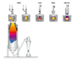
Basic layout of different melting devices used for metal powder production
Vacuum Atomization Powder Production Furnace
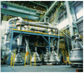
The image on this page shows a large inert gas atomization system. The production capacity of the melting crucible of this atomization system is 2 tons. The atomization tower is connected to the melting chamber through a double crucible door device. Each vacuum induction melting furnace is equipped with a furnace door. This design allows for quick crucible changes. While one crucible is in production, the second crucible is cleaned and relined and is ready for use. This reduces downtime caused by furnace change operations. In addition, the double-door design enhances production flexibility, as different furnace sizes can be used with the same equipment. The melting chamber is equipped with a batch feeder, two temperature measuring devices, and a spare intermediate vessel system.
Each pouring intermediate vessel has a gas nozzle device installed on the intermediate vessel trolley. The intermediate vessel trolley can be moved to a side position for loading and unloading without system discharge and without damaging the surrounding environment. In case of an outlet blockage, the spare intermediate vessel device will have high flexibility. In this case, the second preheated intermediate vessel pouring system in standby will be moved to the atomization position to continue production.
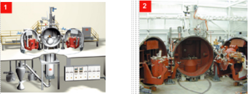
1. Schematic diagram of large atomization device design with double-door furnace chamber,
2. Double-door crucible VIGA atomization device. Each vacuum induction furnace has a rated batch capacity of 2000 kg. 3. The gas recovery system recovers and reuses inert gas.
Ceramic-free metal powder production
The "standard" design of a vacuum induction melting inert gas atomization system includes a ceramic melting crucible, ceramic materials for the intermediate vessel, and a molten metal outlet device. Due to the contact between the molten metal and the ceramic lining and spout materials, ceramic materials will be mixed into the molten metal, which negatively affects the material properties of high-strength PM parts. Reactive metal powders, such as titanium alloys, cannot be produced using this method because a reaction occurs between the reactive molten metal and the ceramic lining. To overcome the "ceramic problem", melting technologies are needed where the molten metal does not come into contact with the ceramic lining material. In addition, this technology is also needed for refining the molten metal during the melting process. Typical materials requiring ceramic-free production processes are refractory and reactive materials such as Ti, TiAl, FeGd, FeTb, Zr, and Cr.
EIGA
In the Electrode Induction Gas Atomization (EIGA) process, pre-alloyed rods in the form of electrodes are inductively melted and atomized without the use of a melting crucible. Electrode melting is achieved by lowering a slowly rotating metal electrode into an annular induction coil. The molten electrode droplets fall into a gas atomization nozzle system, where they are atomized using an inert gas. The EIGA process was originally used for reactive alloys such as titanium or refractory alloys. It can also be used for many other materials.
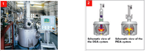
1. EIGA furnace 2. Schematic diagram of EIGA system, schematic diagram of PIGA system
PIGA
For the production of ceramic-free metal powders and the atomization of reactive and refractory metals, a plasma stream can be used for melting in a water-cooled copper crucible. PIGA stands for Plasma Induction Gas Atomization. The bottom of the PIGA shown above is connected to an inductively heated discharge nozzle, which is also made of copper. This ceramic-free discharge nozzle system introduces the molten metal liquid stream into the gas atomization nozzle, where it is dispersed using an inert gas.
VIGA-CC
Reactive metals, such as titanium alloys or intermetallic titanium aluminum compounds, can also be melted in a cold-wall copper induction crucible equipped with a bottom pouring system. The bottom pouring opening of the cold crucible is connected to the CIG system. CIG stands for Cold Wall Induction Guiding system, a patented product of ALD. VIGA-CC stands for Vacuum Induction Gas Atomization based on cold-wall crucible melting technology.
ESR-CIG
High-performance superalloys used in the aircraft industry are generally manufactured using a "triple melting process." In the triple melting process, material refining is carried out using an active slag in the ESR melting step. The combination of ESR remelting technology and a ceramic-free molten metal guiding system (CIG) represents a process technology that produces high-purity and high chemical homogeneity powder materials. In the ESR-CIG (Electroslag Remelting Cold Wall Induction Guiding) process, the material to be atomized is fed in the form of an electrode. The electrode extends downward into the metallurgical refining slag. Because the electrode tip melts at the point of contact with the slag, refined droplets are formed, which pass downward through the active slag layer.
The refined droplets passing through the active slag form a liquid pool under the slag layer. The pool is contained in a copper water-cooled crucible. The refined metal liquid is passed through a cold-wall induction guiding system and then dispersed by a high-velocity inert gas stream from a free-fall gas nozzle.
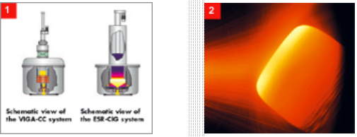
1. Schematic diagram of VIGA-CC system Schematic diagram of ESR-CIG system
Injection molding technology
In addition to being a traditional powder processing method, injection molding has become increasingly important over the past decade. This unique process can be used to directly manufacture semi-finished products. Compared with powder HIP (Hot Isostatic Pressing) technology, it can save a large number of pressing-related process steps, reduce oxygen absorption, and significantly reduce the risk of contamination.
The principle of injection molding technology is to atomize molten metal into droplets and rapidly solidify them onto a collector. By moving this collector, semi-finished products can be gradually formed. Due to the fast cooling rate during the atomization process, a fine microstructure without macroscopic segregation can be obtained. The movement of the nozzle and the design of the collector shape depend on the design of the atomizer, and can produce segmental, annular, tubular, and bar shapes.
The produced semi-finished products must undergo a second processing step, such as: heat treatment, rolling, forging, extrusion, or HIP. This process can be widely used to produce billets with a wide range of applications, such as aluminum alloys, copper alloys, special steels, and high-temperature high-strength alloys for segmental collectors.
Inert gas recovery
In atomization systems with a certain feed container, it is recommended to recover inert gas to reduce the total consumption of inert gas, making the process system more economical. ALD provides two different process technologies for recovering inert gas.
Injection molding process using "OSPREY" double atomizer
Inert gas recovery based on compressor technology
One method of reusing inert gas is to use a suitable compressor device to "drive" the gas into a closed gas circulation loop. After passing through a cyclone separator and filtration system, the "dust-free" gas is repressurized using a two-stage compressor device. The compressor must be airtight to prevent contamination of the circulating inert gas. Behind the compressor, there is a gas buffer bottle to reduce pressure fluctuations during atomization. This produces stable atomization process conditions related to atomization pressure and gas flow rate. The allowable impurity level of the atomization gas is set very low, and the content of oxygen, hydrogen, and nitrogen can be monitored at several points in the gas circulation loop.
For large atomization systems, this type of gas recovery can operate economically at pressures up to 50 bar.
Powder cooling loop in the gas loop system of large atomization systems (including powder transport and separation)
Liquefaction recovery of argon
To obtain higher supply pressure, instead of the recovery concept described above, the principle of liquefying argon by evaporation using liquid nitrogen as a refrigerant will be used. In this case, the two-stage compressor with a pulsation buffer will be replaced by a parallel flow argon liquefier and a set of high-pressure liquid argon pumps.
The high-pressure liquid argon pump sends liquid argon to the high-pressure gas receiver through the evaporator. According to this technology, the supply pressure can reach approximately 100-200 bar.
Practical operating experience with large atomization systems equipped with recovery systems as described above shows that the recovery rate of the two recovery systems is in the range of 90–95%.
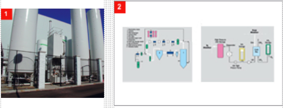
1. Argon liquefaction and recovery system 2. Inert gas recovery system, equipped with a two-stage compressor system, argon liquefaction system layout diagram equipped with a high-pressure liquid argon pump and a high-pressure gas receiver
Features:
1. During the descent of the droplets, rapid solidification overcomes the segregation phenomenon, and the organization is uniform.
2. Using medium-frequency induction heating melting of alloy materials in ceramic or graphite crucibles, effectively purifying through refining and pure flow guiding technology.
3. Using supersonic tight coupling and restrictive atomization nozzle technology, it can realize the preparation of fine powders of various alloy materials.
4. Using a two-stage cyclone classification and collection system design to improve the fine powder recovery rate and reduce or eliminate the emission of fine dust.
Inquiry
Related products